System Control
Decoding instructions - Classic way
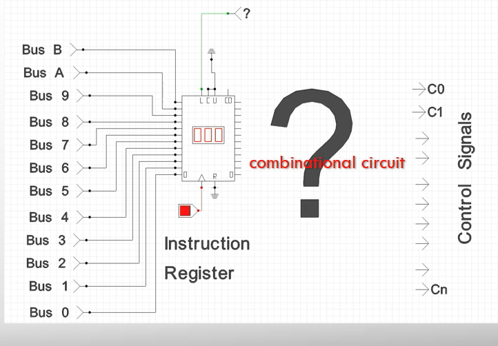
- For each bit combination may lead to a different instruction
- Or better put "Map each control signal onto a separate bit of the instruction word"
- Computers are complicated and words may become too long
- Some combinations may cause damage (3 sate output clashes)
- Most combinations will be useless
- To solve this use could use a smaller number of bits for the control signal, and have that within a larger number of bits needed for the control
- This is all rarely changed, due to such large changes required
Decoding instructions - Memory way
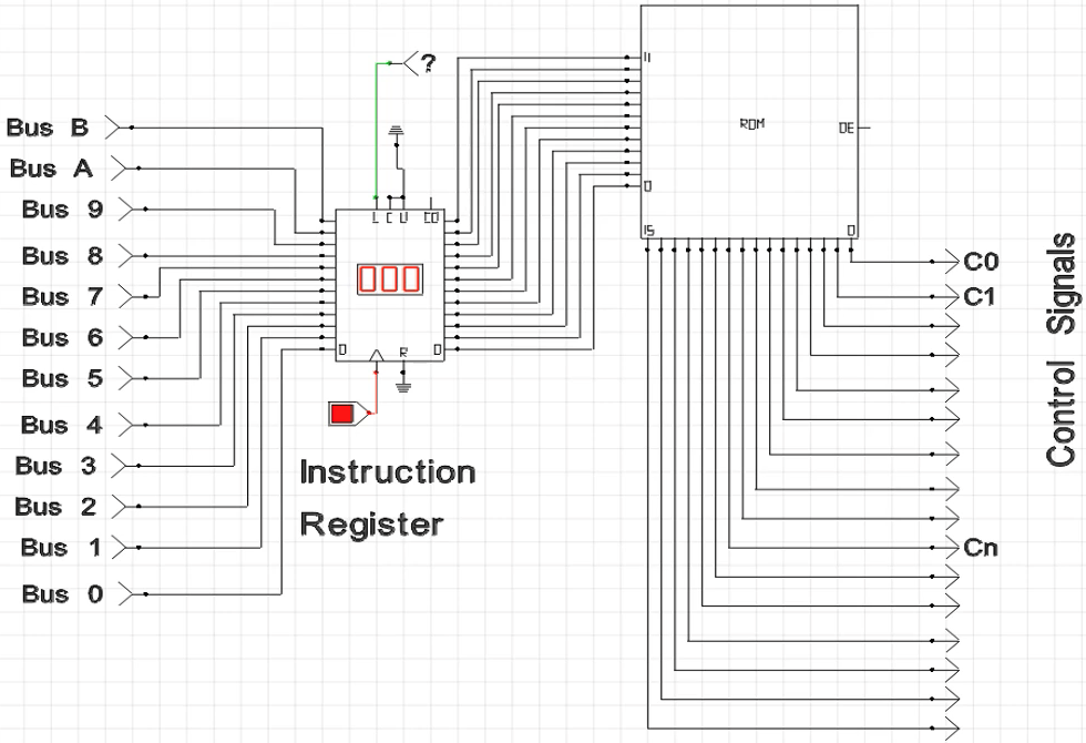
- Control signals are stored in ROM, (acts as a look up table)
- Input the instruction code, this is an address
- Outputs the control signal
- VERY MUCH OVERKILL because there can be loads of input combinations
Decoding - Programmable method
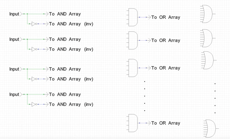
Note: connections are passed from each vertical layer, input left to the output right
- Generalised to create whatever type of outputs from the inputs
- Connections between each layer are different depending out desired outputs
- Used in most programable devices
CPLDs - Complex Programmable Logic Devices
FPGAs - Field-Programmable Gate Arrays (most commonly used)
In practice
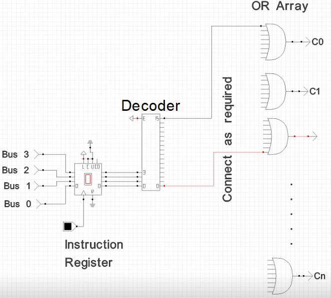
Note: AND gates replaced with a decoder
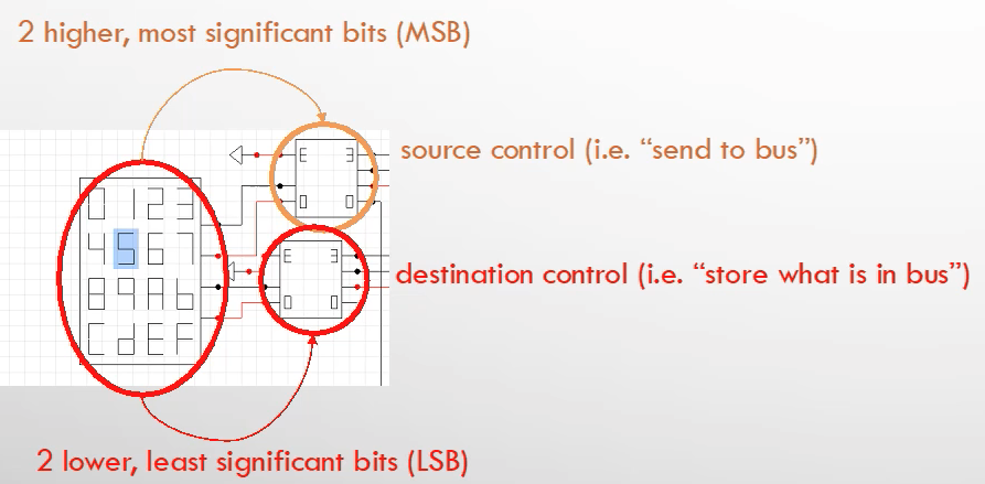
Note: this has two fields, the first two bits and the second two bits
- Most instructions are broken down into several fields (groups of bits that control different tasks)
Bringing it all together
Harvard
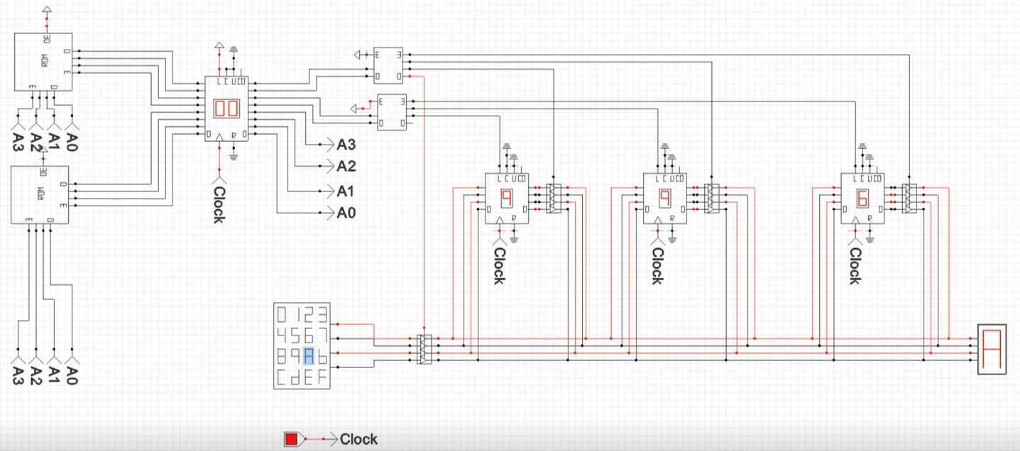
- ROMs contain the lookup tables, for sources and destinations and next instruction
Von Neumann
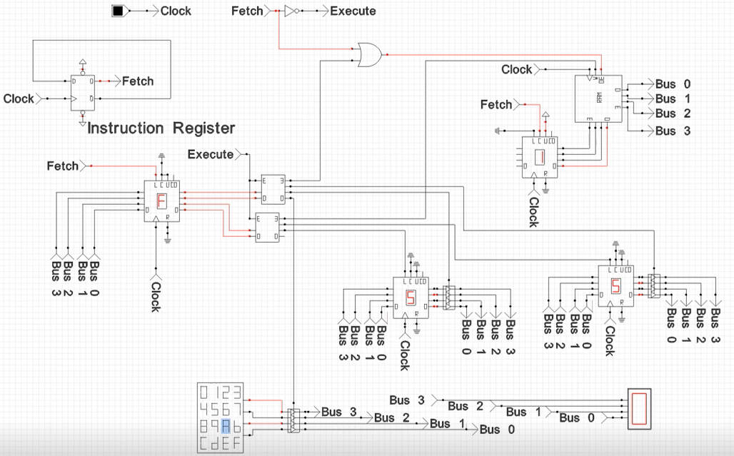
- Remember there is a fetch cycle and a execute cycle