UML & OMT diagrams
I RECOMMEND READING THIS ^^^^ AND NOT BOTHERING WITH THIS PAGE
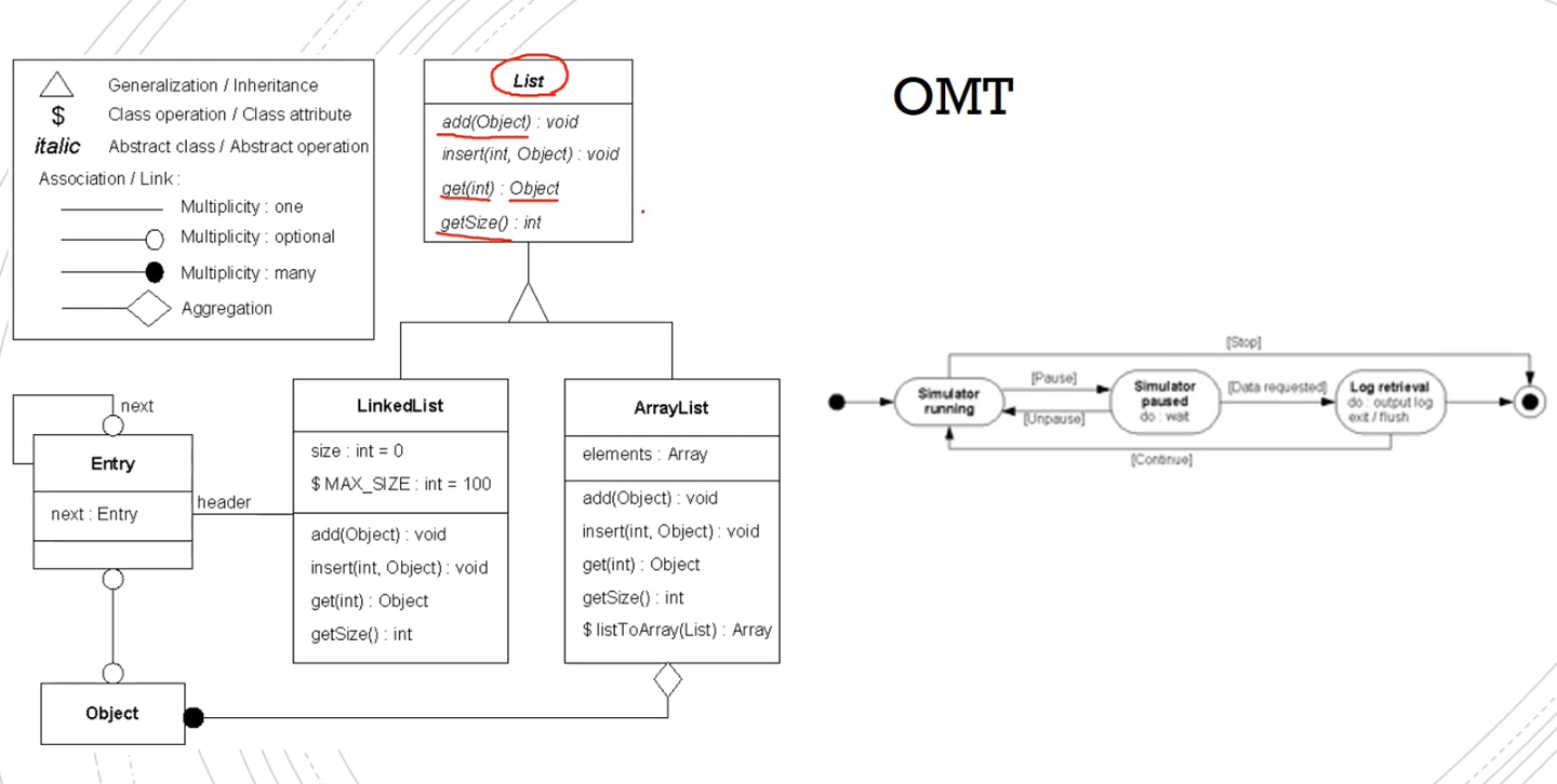
Object-modeling Technique
A way of designing objects to see how they work together in the software.
Allows for:
- Testing physical entities before building them (in a simulation)
- Helps with communication with customers
- Abstracts the complexity of the applicatopn
Object model - Shows the objects and classes with their relationships.
Dynamic model - Shows the transition between states and the events to tigger the transitions.
Functional model - Shows the data flow, how data is processed and the actors involved.
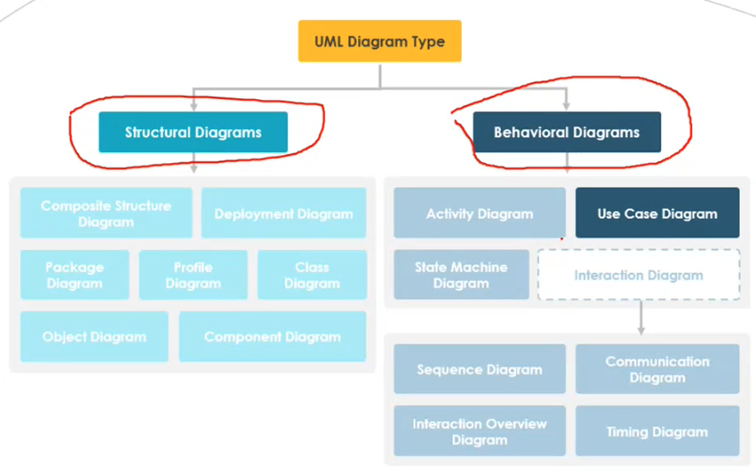
Unified Modelling Language
Very good for documentation and visualisation of the software.
Types of diagram
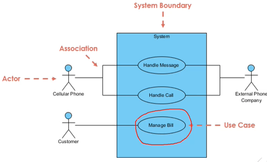
Use-case
Only shows the functional requirements, and is the primary source of the software requirments.
Says what, not really how it will happen (no technical detail).
- Specify context
- Capture requirments
- Validate system architecture
- Helps with implementation and tests cases
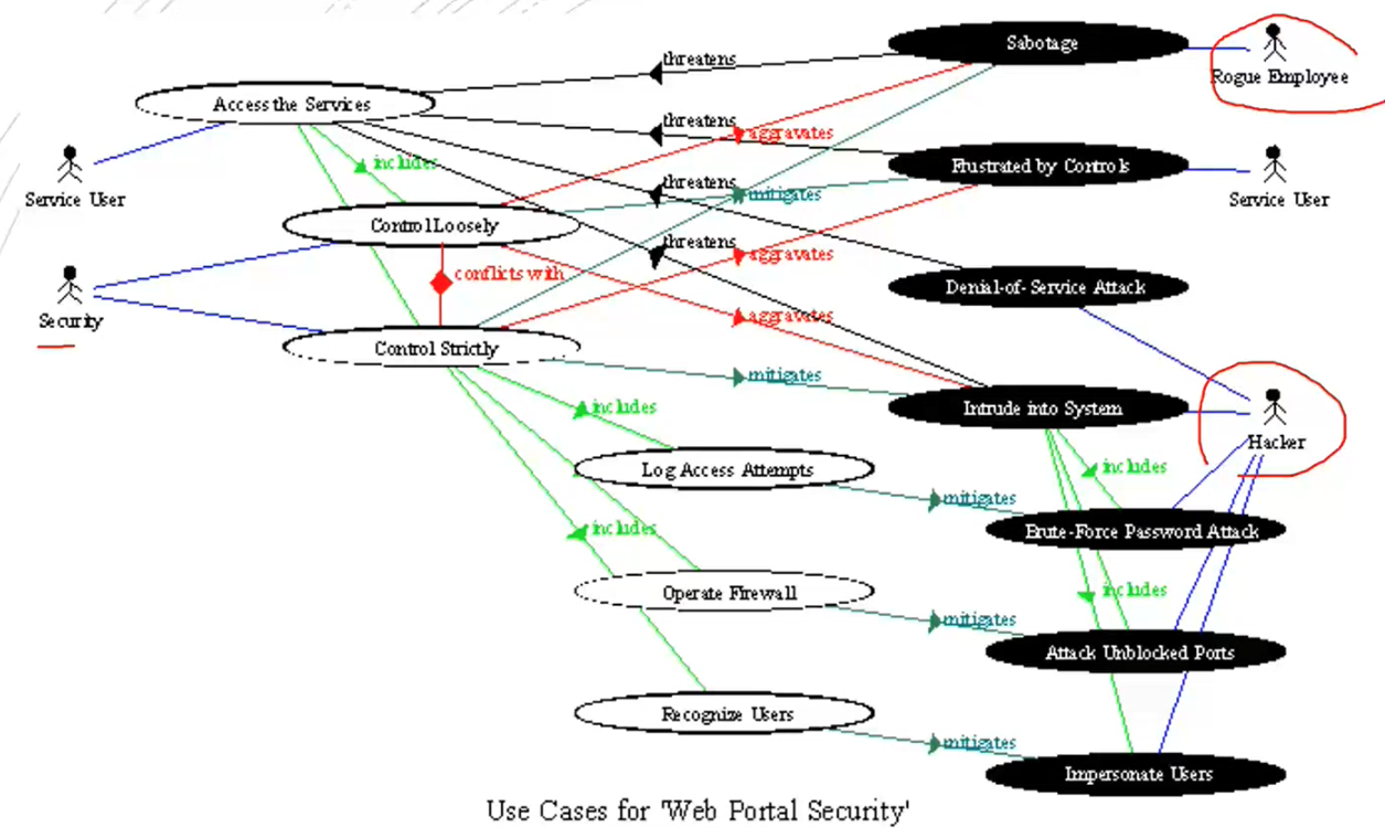
Should be simple enough to read that the customer can read it.
No more than 20 use-cases.
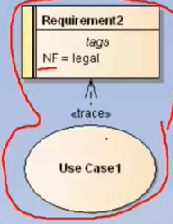
They are typically traced back to a non-functional requirement - i.e. is it quick enough.
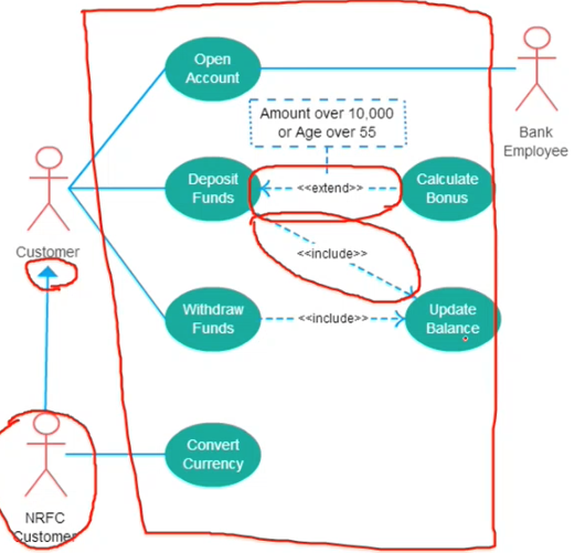
<<extends>> - The base of the arrow is within the pointy end of the arrow
<<include>> - The one being pointed at will include the functionality of the one where the arrow is coming from

^^^ parent ^^^ child
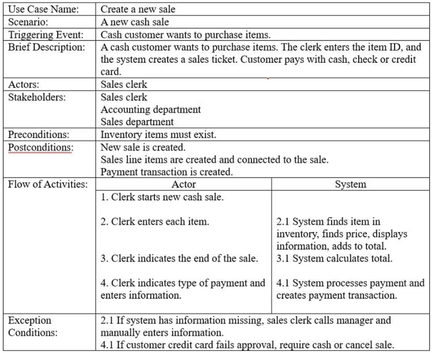
Use case description
Activity Diagram
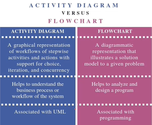
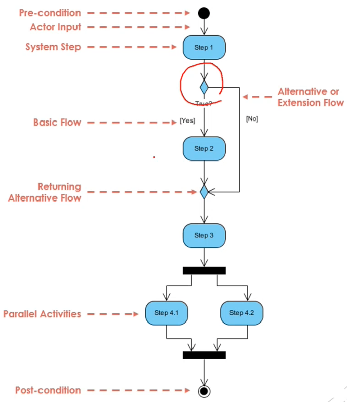
Note: the black square means create/close fork